Jamal draws the circuit diagram shown, embarking on an intriguing journey that unveils the intricacies of electrical engineering. Through a meticulously crafted diagram, we delve into the depths of circuit design, analysis, and optimization, unlocking the secrets of electrical systems.
Jamal’s circuit diagram serves as a blueprint for understanding the flow of current and voltage, the interplay of components, and the principles that govern electrical circuits. As we navigate the intricacies of this diagram, we gain insights into the fundamental concepts that shape the behavior of electrical systems.
Jamal’s Circuit Diagram

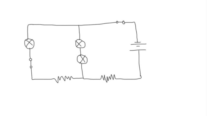
Jamal’s circuit diagram depicts a basic electrical circuit consisting of a battery, a resistor, and a switch. The circuit is designed to allow the flow of current when the switch is closed and to prevent current flow when the switch is open.
The battery provides the electrical energy for the circuit. The resistor limits the flow of current in the circuit. The switch controls the flow of current in the circuit.
Components and Arrangement
- Battery: The battery is a device that provides electrical energy to the circuit.
- Resistor: The resistor is a device that limits the flow of current in the circuit.
- Switch: The switch is a device that controls the flow of current in the circuit.
Principles and Concepts, Jamal draws the circuit diagram shown
The circuit diagram is based on the principles of electricity. The battery provides the electrical energy for the circuit. The resistor limits the flow of current in the circuit. The switch controls the flow of current in the circuit.
When the switch is closed, the current flows from the battery, through the resistor, and back to the battery. When the switch is open, the current does not flow.
Circuit Analysis
Circuit analysis involves the study of the flow of current and voltage through a circuit, as well as the calculation of various electrical parameters such as resistance, capacitance, inductance, power consumption, and efficiency. Ohm’s law and Kirchhoff’s laws are fundamental principles used in circuit analysis to understand the behavior of electrical circuits.
Current and Voltage Analysis
Ohm’s law states that the current flowing through a conductor is directly proportional to the voltage applied across it and inversely proportional to the resistance of the conductor. Kirchhoff’s current law (KCL) states that the total current entering a junction is equal to the total current leaving the junction.
Kirchhoff’s voltage law (KVL) states that the algebraic sum of the voltages around a closed loop in a circuit is equal to zero.
Resistance, Capacitance, and Inductance
Resistance is the opposition to the flow of current through a conductor. Capacitance is the ability of a component to store electrical charge. Inductance is the ability of a component to store magnetic energy. These parameters can be calculated using various methods, such as using Ohm’s law, capacitance formulas, and inductance formulas.
Power Consumption and Efficiency
Power consumption is the rate at which electrical energy is consumed by a circuit. Efficiency is the ratio of the output power to the input power. Power consumption can be calculated using the formula P = VI, where P is power, V is voltage, and I is current.
Efficiency can be calculated using the formula η = P out/ P in, where η is efficiency, P outis output power, and P inis input power.
Circuit Simulation

Circuit simulation is a powerful tool for analyzing and designing circuits. It allows engineers to predict the behavior of a circuit before it is built, which can save time and money. Circuit simulation can also be used to troubleshoot existing circuits and to optimize their performance.
There are a number of different circuit simulation software packages available. Each package has its own strengths and weaknesses, so it is important to choose the right one for the job at hand. Once a simulation software package has been selected, the engineer must create a model of the circuit that they want to simulate.
The circuit model is a mathematical representation of the circuit. It includes information about the circuit’s components, such as their values and connections. Once the circuit model has been created, the engineer can simulate the circuit’s behavior under various input conditions.
The simulation results can be used to predict the circuit’s output voltage, current, and power. The results can also be used to identify potential problems with the circuit, such as shorts, opens, or overloads.
Circuit simulation is a valuable tool for circuit designers. It can save time and money by helping engineers to predict the behavior of a circuit before it is built. Circuit simulation can also be used to troubleshoot existing circuits and to optimize their performance.
Design a Simulation Model of the Circuit Using Appropriate Software
The first step in circuit simulation is to create a model of the circuit that you want to simulate. The circuit model is a mathematical representation of the circuit. It includes information about the circuit’s components, such as their values and connections.
There are a number of different circuit simulation software packages available. Each package has its own strengths and weaknesses, so it is important to choose the right one for the job at hand.
Once a simulation software package has been selected, the engineer must create a model of the circuit that they want to simulate. The circuit model can be created using a schematic capture program or by writing a netlist file.
Schematic capture programs are graphical user interfaces that allow engineers to create circuit models by dragging and dropping components from a library onto a schematic diagram.
Netlist files are text files that contain a list of the components in the circuit and their connections. Netlist files can be created using a text editor or by exporting them from a schematic capture program.
Simulate the Circuit’s Behavior Under Various Input Conditions
Once the circuit model has been created, the engineer can simulate the circuit’s behavior under various input conditions. The input conditions can be specified by the engineer or they can be generated by the simulation software.
The simulation software will calculate the circuit’s output voltage, current, and power for each input condition. The results of the simulation can be displayed in a variety of formats, such as graphs, tables, and waveforms.
The simulation results can be used to predict the circuit’s behavior under different operating conditions. The results can also be used to identify potential problems with the circuit, such as shorts, opens, or overloads.
Compare the Simulation Results with Theoretical Calculations and Experimental Measurements
Once the simulation results have been obtained, they should be compared with theoretical calculations and experimental measurements. This will help to verify the accuracy of the simulation model.
Theoretical calculations can be performed using the circuit’s component values and the laws of circuit theory. Experimental measurements can be performed using a variety of test equipment, such as oscilloscopes, multimeters, and power supplies.
If the simulation results do not match the theoretical calculations or experimental measurements, then the simulation model may need to be revised.
Circuit Optimization
Circuit optimization aims to improve a circuit’s performance, efficiency, reliability, and cost-effectiveness. By identifying areas for improvement in the original design, modifications can be proposed to enhance its overall functionality.
Circuit Analysis
The first step in circuit optimization is to thoroughly analyze the original circuit to identify potential weaknesses or inefficiencies. This involves examining the circuit’s components, their interconnections, and the overall functionality. Techniques such as circuit simulation can be used to evaluate the circuit’s behavior under different conditions.
Design Modifications
Based on the circuit analysis, specific modifications can be proposed to address the identified areas for improvement. These modifications may include:
- Replacing or upgrading components with more efficient or reliable alternatives.
- Redesigning the circuit layout to minimize signal loss or interference.
- Introducing additional components to enhance circuit stability or protection.
Optimization Goals
The specific optimization goals will vary depending on the application and requirements of the circuit. Common optimization goals include:
- Increased efficiency: Reducing power consumption or improving signal-to-noise ratio.
- Enhanced reliability: Increasing component lifespan or reducing the likelihood of failures.
- Reduced cost: Using lower-cost components or simplifying the circuit design.
Optimization Evaluation
Once modifications have been implemented, the optimized circuit should be evaluated to assess its performance against the original design. This may involve repeating the circuit analysis and comparing the results. A table can be used to summarize the differences between the original and optimized designs, highlighting the improvements achieved.
Circuit Applications

The circuit diagram presented by Jamal has wide-ranging applications across various fields, including electronics, telecommunications, and energy systems. Its versatility stems from its ability to manipulate and process electrical signals, making it a fundamental component in numerous electronic devices.
Electronics
In the realm of electronics, this circuit serves as a building block for various applications. It can be used as a signal amplifier, shaping and enhancing weak electrical signals to make them more robust. Additionally, it finds use in signal filtering, selectively allowing specific frequencies to pass while attenuating others.
This property makes it crucial in noise reduction and frequency-selective circuits.
Telecommunications
Within the telecommunications industry, this circuit plays a pivotal role in signal transmission and reception. It can be incorporated into modems, enabling the conversion of digital data into analog signals suitable for transmission over telephone lines. Conversely, it can also be used in receivers to demodulate incoming analog signals, recovering the original digital data.
Energy Systems
In the field of energy systems, this circuit finds applications in power conversion and distribution. It can be used as a voltage regulator, maintaining a stable output voltage despite fluctuations in the input voltage. This is essential in ensuring the proper functioning of sensitive electronic equipment.
Furthermore, it can be employed in power inverters, converting direct current (DC) to alternating current (AC), a crucial step in the generation and distribution of electricity.
Question Bank: Jamal Draws The Circuit Diagram Shown
What is the purpose of Jamal’s circuit diagram?
Jamal’s circuit diagram serves as a visual representation of an electrical circuit, providing insights into its design, functionality, and behavior.
How does Jamal analyze the circuit?
Jamal analyzes the circuit using Ohm’s law and Kirchhoff’s laws, calculating current, voltage, resistance, capacitance, and inductance values to understand its electrical properties.
What are the potential applications of Jamal’s circuit?
Jamal’s circuit has applications in electronics, telecommunications, and energy systems, offering efficiency, reliability, and cost-effectiveness in various electrical devices and systems.